Following on from the previous post where we made a small repair section for the forward end of the keel and cut scarfs to fit now we fit it into place....
With the section in place holes were drilled for the new bolts and 3/8" bronze threaded rod used to make them. The existing bolt holes through the fore deadwood and hog were re-used
Bedding compound was made up in the traditional manner by mixing red-lead with linseed oil putty thinned with raw linseed oil.
The bolts were sealed by smearing them with bitumastic compound and a cotton grommet and everything was bolted-up tight.
 |
| Ingredients for making re-lead putty |
 |
| Red-lead putty mixed and ready |
 |
| New section of keel being offered-up |
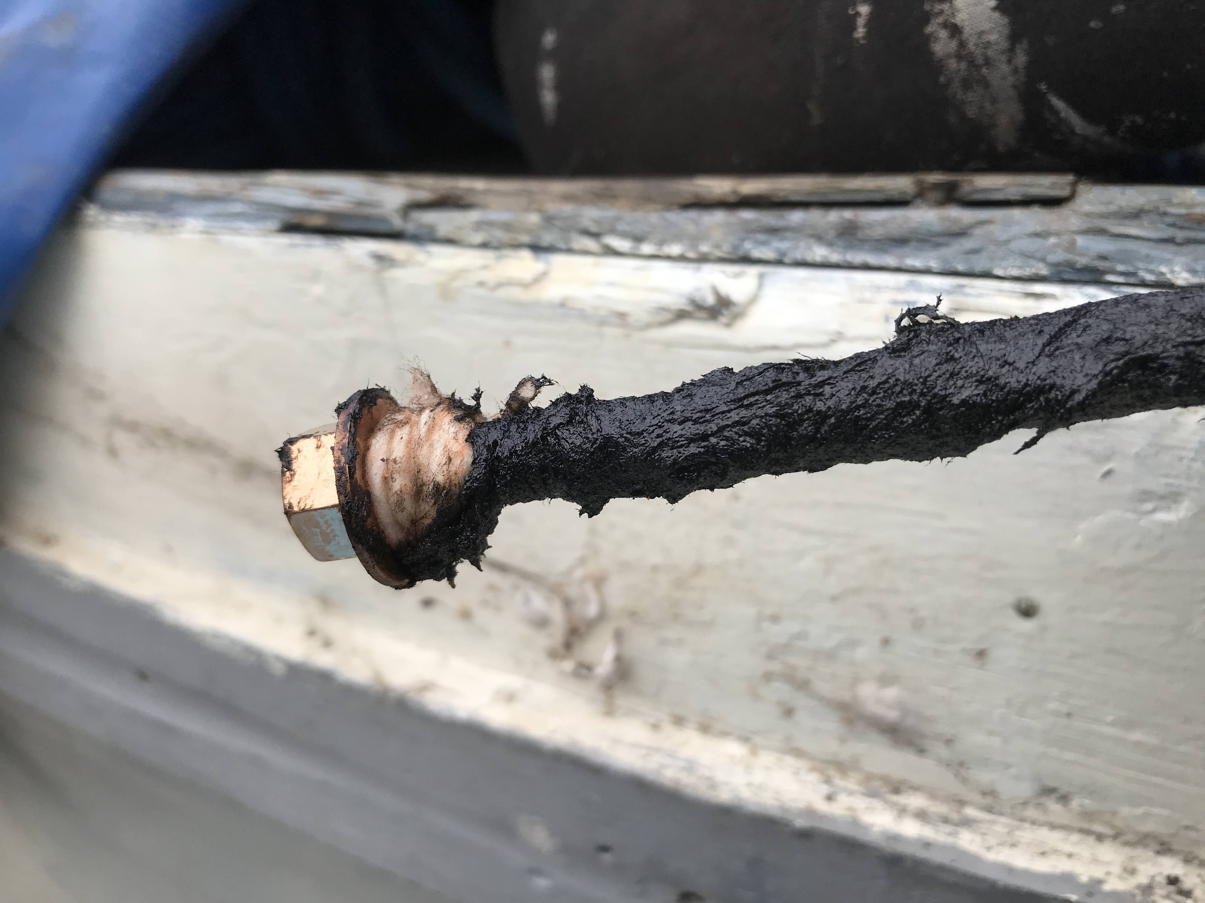 |
| Bronze bolts sealed with bitumastic and cotton |
 |
| Bolted up tight |
There was a smaller section of timber right on the curve of the forefoot that was crumbling from being encased in the iron 'shoe'. This again was a later addition and presumably a repair after past damage.
With the old bit of timber chipped away the remains of the fixing screws were extracted and the remaining timber cleaned-up. A new piece was cut from the remaining oak and once a snug fit was achieved the mating surfaces were primed with sealing epoxy.
 |
| Forefoot having a clean-up for a new piece of timber to be fitted |
At this stage in our works the weather got colder and wetter and the virus pandemic halted our works.
I have continued with some small jobs such as priming and varnishing bare wood inside the boat and doing some jobs on the engine.
 |
| Varnishing - 3-coats for now to seal and protect the new timber |
The Dorman engine is missing its dynamo and instead the drive shaft - which is an extension of the governor shaft - had been fitted with a 'V' belt pulley but no clue as to what it drove. Looking at the engine's drawings it appears that this shaft runs in plain bearings that are splash-lubricated inside the gearcase; hence this shaft is not really suitable for a radial load that a 'V' belt drive would apply. Originally a C.A.V. dynamo was coupled to this shaft and directly driven.
I have been hunting for the 'correct' D45R dynamo for a while without success but then realised that the '45' means a 4 1/2" body diameter and instead a Lucas type C45 dynamo would fit and would have a low enough 'cutting-in' speed. To check this before splashing out on a suitable machine I made a cardboard mock-up to check for fit on the engine - which it does.
 |
| Cardboard mock-up Lucas C45 dynamo to check for fit. The oil pressure gauge is temporary. |
Now I have obtained an enclosed (i.e. non-ventilated) C45 dynamo with a 1955 date that was probably from a tractor. To fit it to the engine I have to make some clamping straps and a coupling hub as the drive is basically a short piece of 1 3/4" rubber hose secured by hose clips. The drive hub is on order as it has to be made specially and I've no access to a metalwork lathe.
 |
| This pulley had been fitted to the drive hub |
 |
| Pulley removed to leave the 1 3/4" spigot - this turns at 1.4 times engine speed |
The engine is also missing its 'dashboard'/control panel on which controls and instruments are mounted. I have a tachometer and have obtained throttle control lever, oil pressure gauge, ammeter and various buttons and switches and the current job is the manufacture of the mounting board, roughly copying the illustrations and drawings in the engine manual. I have made a frame from 1" angle to support a panel and this is as far as I've got now.
 |
| This is what it should look like |
 |
| Control panel manufacture underway |
Just before Christmas 2020 a timber supplier I occasionally order from was offering 1m3 bundles of sapele offcuts. I purchased one and a whole stack turned up so now we've got sufficient timber for pretty much all the internal joinery and also the framing for the cuddy and cabin top.
 |
| Plenty of sapele - most of these are more than 4m long. |
No comments:
Post a Comment